
Air Bearing Principles: Flow Restriction and Supporting Film
2026-11-06
Air Bearing Principles: Flow Restriction and Supporting Film
Air Bearing Principles explain support through a thin film of pressurised gas between surfaces that would otherwise touch. In the externally supplied arrangements discussed here, air passes through a delivery structure into the bearing gap and continues escaping around the edges. The bearing face, flow restriction and guide surface therefore belong to one supporting relationship.
The air film is the load-bearing interface
IBS Precision Engineering's official air-bearing FAQ defines an air bearing through moving surfaces kept apart by a layer of air. It describes the film as a low-friction load-bearing interface. The separation is doing mechanical work in the explanation rather than providing an empty clearance around an otherwise conventional rolling bearing.
A conceptual section can therefore identify two solid surfaces and the air layer between them. The bearing member and the guide surface should remain distinct from that layer. Drawing the gap larger for clarity does not assign an actual operating clearance or describe the load capability of an unknown bearing.
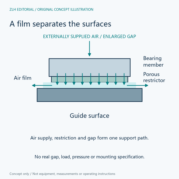
A porous face meters and distributes the supplied air
The IBS FAQ explains that porous-media bearings supply air through many small passages distributed across the bearing surface. Its structural illustration separately labels the metal housing, air distribution region, porous restrictor and air gap. These names identify different parts of the path from the external supply to the supporting film.
The porous material is consequently part of the delivery and restriction mechanism. It is not merely a protective layer placed over an unrelated set of rollers. The pressure and flow relationships in the gap depend on how air reaches the face and how it leaves the interface.
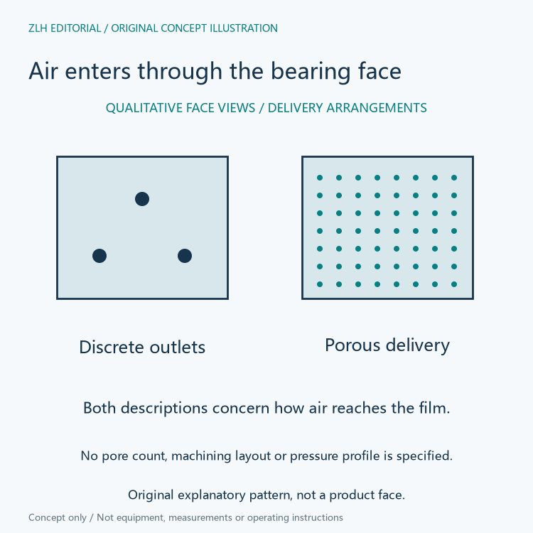
Discrete outlets form another delivery arrangement
The same FAQ contrasts porous media with an orifice arrangement. In the latter, air is supplied through precisely sized holes on the bearing surface, sometimes combined with distribution grooves. In the porous arrangement, delivery is spread through the material across the face.
This comparison concerns the route into the film. It does not mean that every visible hole in a machine plate is an air-bearing outlet, or that the delivery category supplies a universal performance result. The corresponding bearing reference connects the actual geometry with its specified characteristics.
The gap and applied load remain related
IBS describes a relationship between loading, the gap and pressure in the film. It explains that the gap becomes smaller as its porous bearings are loaded and discusses lift-load curves for particular input conditions. The supporting film is therefore not a rigid spacer with one fixed clearance independent of load.
The FAQ also identifies continuing air leakage at the edges. That feature helps explain why a simple area multiplied by a supply-pressure number is incomplete as a description of an actual bearing. Its documented load relationship must retain the bearing geometry and applicable input conditions.
IBS explains that a lift-load curve connects the fly height with a given load at a given input pressure, and relates the curve's gradient to stiffness under those conditions. Height and stiffness therefore express different aspects of the supporting relationship. One quoted clearance does not replace the associated load-dependent account.
Support, drive and position feedback have separate jobs
PI's official PIglide air-bearing technology explanation describes a moving carriage supported by an air bearing together with a direct-drive motor and a high-resolution encoder. The bearing provides support and guidance, while the motor and position feedback belong to the complete positioning system.
This is useful when reading an equipment offer containing an air-bearing stage. The bearing name alone does not identify its actuator or encoder. Conversely, an encoder entry does not describe the surface-support mechanism. A clear inventory keeps these components associated with the same identified stage rather than allowing one attribute to stand for the entire system. PI's range includes both linear and rotational arrangements, so the direction and form of the supported motion also belong beside the specific stage identity.
The air supply and environment stay in the explanation
PI states that its air-bearing arrangements require a continuous supply of clean compressed air or nitrogen. Its environmental discussion also distinguishes relatively clean applications from conditions with substantial debris or liquids. The non-contact supporting principle does not remove those surrounding system conditions.
The references discuss vacuum use with different engineering emphasis: IBS describes applied examples, while PI describes the challenge and relevant limitations. Neither description makes an unspecified bearing universally suitable for a vacuum installation. Related material appears in the precision motion equipment collection and technical article directory. The original figures explain the supplied film and delivery arrangements without prescribing a pressure, gap or assembly method.